One of my major interests in photocatalytic water splitting. There are a couple of major fundamental issues holding back the renewable energy field. The first is that there are very few renewable energy sources that provide sufficient enough energy to supply societies demand. Currently we consume about 18 TW worth of energy and predictions are that we will consume 30 TW by 2050. Wave technology, geothermal, and most other renewable energy sources can't supply the world with this amount of energy. Depending upon estimates wind may or may not be able to produce 30 TW. However 120,000 TW of solar energy strike the earth each day, thus solar energy is the one renewable energy source that clearly can fulfill our energy demands.
However like most renewable energy sources, solar power is intermittent. In other words, solar power doesn't work at night, so what do you do then? Biological systems have resolved this issue millions of years ago by converting sunlight into molecular fuels, such as sugars. While it took them millions of evolution, their overall efficiencies are still less than 1%.
Approach to Photocatalytic Water Splitting
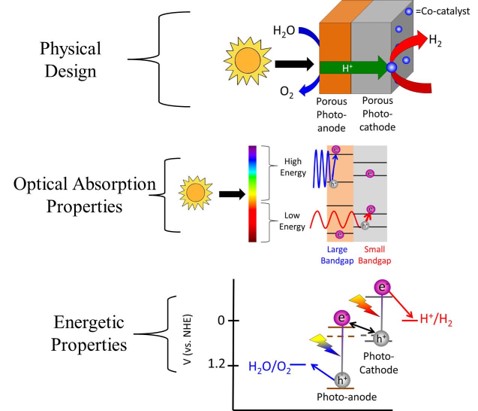
My current approach to producing renewable energy is also by taking sunlight and directly converting it to molecular fuels, however I use inorganic materials rather than the organic materials that are used in biological processes. Inorganic materials are, in general, much more stable than organic molecules, which gives some significant advantages to this approach. While photo-biological processes produce hydrocarbons, in my work I simply focus of using solar energy to split water into hydrogen and oxygen. Hydrogen can be stored as a fuel, and then used via either a fuel cell or combustion when it is needed. While the biologically produced hydrocarbons are easier to store than hydrogen, the hydrogen reaction is much simpler. The simplicity in this reaction allows for more efficient catalysis, and thus a more efficient reaction.
The water splitting reaction is as followed:
H2O → H2+O2
However photochemically (or electrochemically) this can be broken down into 2 'half reactions' as shown below.
Anodic half reaction: H2O → O2+2H++2e-
Cathodic half reaction: 2H+ → 2e- + H2
One important difference between the anode and the cathode is that the electron in the cathode is thermodynamically 1.23 eV higher in energy than that in the cathode. Thus to get this reaction to work you need an energy source of 1.23 eV. Thus one would think photocatalyst with a band gap of 1.23 eV or larger should be absorb photons and use that energy to split water. However in reality there are Carnot efficiency losses and entropic losses in the photocatalyst, which correspond to ~300 mV. In reality the losses will probably be closer to 400-500 mV due to engineering constraints. Furthermore both the anode and cathode half reactions will have some loss due to inefficient catalysis. Researchers have been studying these reactions for decades and the even with the best catalysts there are still ~350 mV loss on the anode and 30 mV on the cathode. There are also ohmic losses relating to the electron and more importantly the proton transferring from one electrode to the other. Thus in reality you need a photocatalyst with a band gap of at least 2.1-2.3 eV.
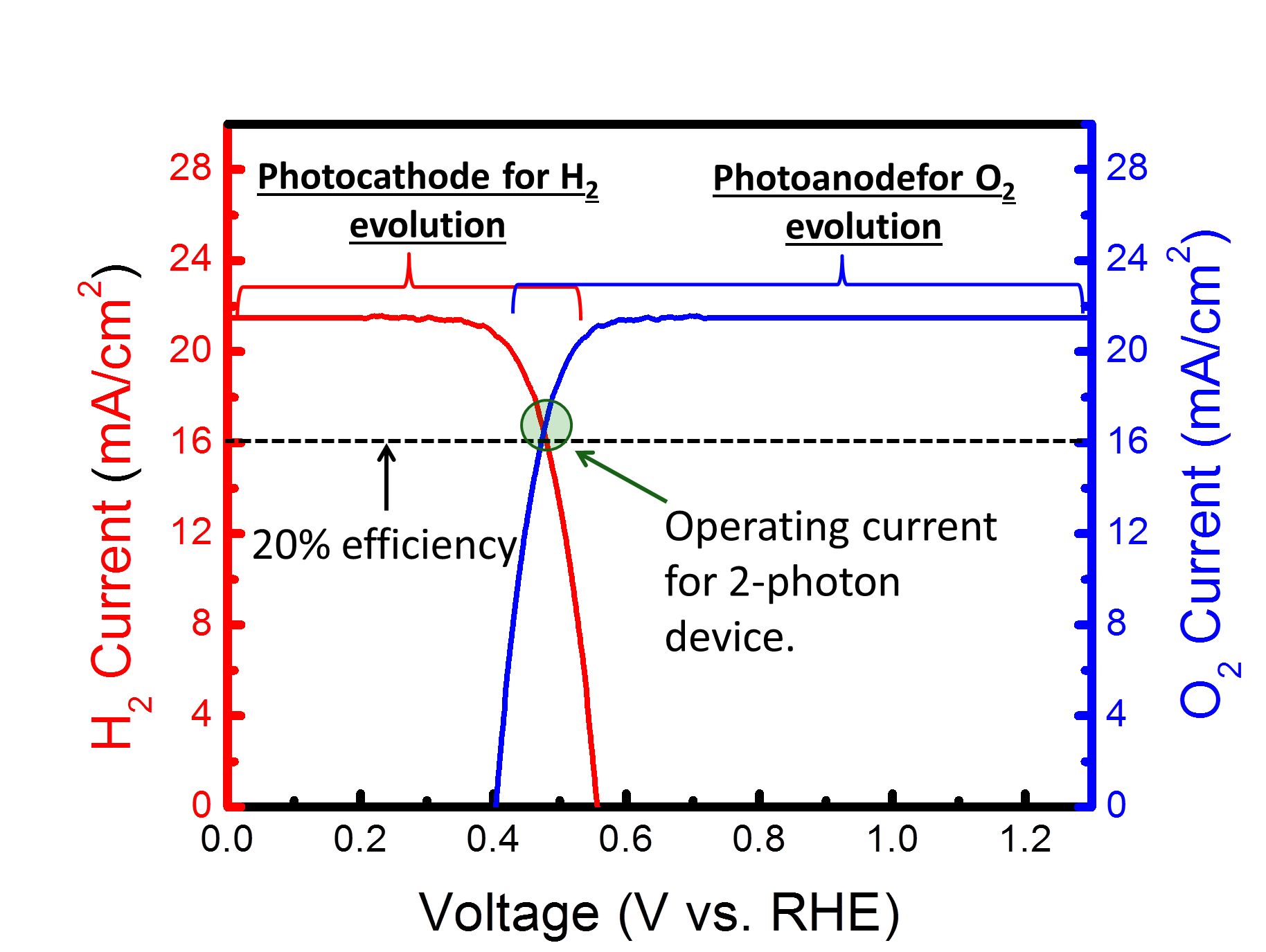
Simplifying the Experiments Rather than try to build a 2-photon water splitting device all at once, it is possible to break this device down into 2 separate photoelectrochemical reactions: 1) Photoanodic O2 evolution and 2) Photocathodic H2 evolution. The great thing about photoelectrochemical reactions is that one can use a potentiostat to control the potential (i.e. Fermi level) of the semiconductor. Thus we can see how both the photoanode and photocathode perform at different potentials. From the energy diagram above it can be seen that eventually both the photoanode and photocathode will need to be at the same potential for overall water splitting to occur. Thus by plotting both the photoanode and photocathode current as a function of voltage on the same graph, the intersection between the 2 curves will be the current at which the device will operate at. The figure below shows this general concept. Current can be converted to amount of hydrogen via Faraday's constant and dividing by 2 since 2 electrons are needed per mole of H2.
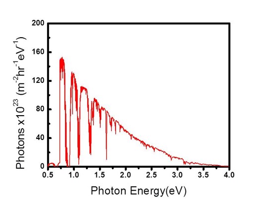
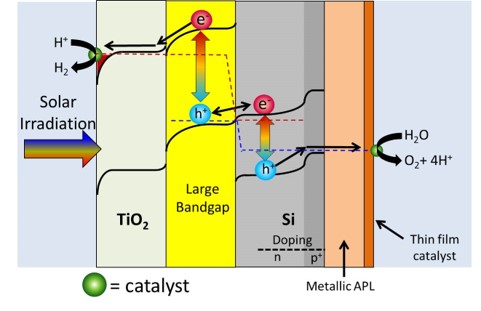
Just as a reference, 16 mA/cm2 corresponds to about 20% solar to hydrogen efficiency. By only focusing on one photocatalyst at a time, it is much easier to analyze and then optimize the catalyst. Thus in almost all the work I am a part of, we simply focus on either the photoanode or photocathode and look to optimize that reaction. When we get to the point where the crossover between the photoanode and photocathode is respectably high, we will then put together the total device. We are not at that point yet. Our Research-Past One important point that really complicates things is issues relating to ohmic losses due to ionic transfer. This issue is well known in the electrolyzer field, and a recent (report shows it can also be a major issue for photocatalytic water splitting. Basically neutral pH has low ionic conductivity even if you add a large amount of ionic species. However highly acidic or highly basic solutions can take advantage of water's ability to dissociate into H+ or OH-, and can be much more conductive. This allows for ohmic losses to be greatly reduced. However these extreme pH's one must go to also causes stability issues with many photocatalysts. Simply put, few photocatalysts are stable in extreme pH conditions. Many photocatalysts also struggle to stay stable in either the highly reductive potentials needed for hydrogen evolution or the highly oxidative potentials needed for oxygen evolution. Since stability is a function of both pH and potential, Pourbaix diagrams are quite useful in looking for thermodynamically stable materials. As our recent analysis work has shown, finding thermodynamically stable materials for 2 photon water splitting is quite difficult. However there is a way around this stability issue. Using protection layers dissociates the stability issue from the photocatalyst issue. Thus, in effect, we can have a great photocatalyst that doesn't need to be stable as long as it has a valid protection layer. Our first foray into protection layers was trying to protect a Si photocathode. With a band gap of 1.1 eV, Si is almost a perfect small band gap material. However Si oxidizes to the insulating SiO2 very easily, which makes it extremely difficult to use in water splitting applications. Our approach was to sputter on a thick enough layer of titanium metal to protect the Si, but yet thin enough to allow light to pass through. This approach was relatively successful, but the Ti absorbed light and did fall off after some time. To resolve this issue we used a thick sputtered TiO2 layer instead. (Importantly we still kept in a small amount of Ti so the TiO2 didn't oxidize the Si.) TiO2 was successful for a couple of reasons. First it is naturally n-type which means charge transfer is primarily via electrons going through its conduction band. Secondly the location of the conduction band is almost perfectly aligned with that of the H2 evolution potential. Thirdly is that TiO2 tends to naturally have a high doping level, which increases its conductivity. Since the protection layers was on the order of nanometers, the TiO2 was conductive enough to not cause any noticeable ohmic resistance. The Si with sputtered TiO2 worked perfectly for 3 days with no stability issues. The Si was only irradiated with small energy photons (to accurately portray its use in a 2-photn device), thus there was no photoexcitation of the TiO2. At a later date in collaboration with the Gratzel group we used atomic layered deposition of TiO2 and tested the device for 30 days with no noticeable stability issues related to the Ti or Si. However in these works we were irradiating from the side of the Si facing the electrolyte. However for a 2-photon tandem device the light will actually be irradiating from the backside of the small band gap Si (See cartoon above showing 2-photon design). Irradiating light from the backside is not trivial because the backside needs to absorb light and the front side needs to do catalysts, thus there is nowhere to put an electrical contact to test how well the device is performing. Furthermore when the Si is irradiated from the backside the light absorption is on the opposite side from the catalysts thus making charge transfer slightly more complicated. However we resolved both the electrical contact issue as well as found the optimal compromise between light absorption and charge transfer and published our results. There was also another property of TiO2 in which we were not fully taking advantage of: its transparency. TiO2 has a band gap of 3.2 eV (for anatase) and by looking at the above figure which plots photons vs photon energy, it should be apparent that TiO2 absorbs very little of the solar spectrum. However, if you review the scheme of a 2-photon device (see above figures), you will realize that since Si is a small band gap material, the protection layer will be on the opposite side of the incoming light. Thus TiO2 transparency means little on the backside of the device. It would be much more interesting if we could protect the large band gap material because in that case having a transparent protection layer is the utmost importance. While the above figures show H2 being produced on the small band gap and O2 being produced on the large band gap, we thought if we switch the reactions around (i.e. H2 produced on the large band gap material) we could take advantage of TiO2's transparency. As a model system we used GaP as a large band gap material to evolve H2. We showed that this material could achieve H2 evolution without a TiO2 protection layer, but it corroded rapidly. Once we added the TiO2 protection layer we mitigated corrosion issues. Unlike Si, GaP is not a highly researched material and thus it is not easy to make p-n junctions to maximize photovoltage. However from this work we found that the p-GaP and n-TiO2 actually form a p-n junction, which helps to boost photovoltage. With the photocathode protection layer under control, we moved onto looking at protection layers for the photoanodic O2 evolution reaction. With the idea of using the large band gap material to evolve H2, that leaves the small band gap material to evolve O2. Thus we looked at protecting our Si with protection layers. We initially thought that Ti could not be used as a protection layer since we showed that at anodic potentials, the TiO2 prevented any charge transfer due to band bending effects. However we realized that since Si is on the side opposite from the incoming light, light absorption is of minor concern. This allowed us to deposit a thin Ir/IrO2 protection layer. Given that IrO2 is the only stable O2 evolution catalyst in acid, this allowed us to produce a combined protection layer/O2 evolution catalyst all in one. We also took this same approach for protection layers in basic conditions. In this case we used a Ni/NiO for a protection layer/O2 evolution catalyst. Since NiO is inherently not a very good O2 evolution catalyst, we cycled our device in a ferrous solution. This allowed us to produce Fe intercalated NiO, which is one of the best O2 evolution catalysts. A provocating result
by the Lewis group, led us to rethink TiO2 as
an anodic protection layer. From this we
discovered that as long as TiO2 was
covered by a film of catalyst, the TiO2 would
interact with the film and not the electrolyte.
Evaporation of our Pt catalyst onto TiO2 gave
us a Shottky barrier and thus prevented charge transfer,
however sputtering Pt onto TiO2 gave us an
ohmic contact and thus this ohmic contact allowed us to
use TiO2 as an anodic protection layer.
(It should be noted that Gary
Hodes was the first one to discover that evaporated
Pt-TiO2 form a Schottky barrier whereas
sputtered Pt-TiO2 forms an ohmic contact.
While he presented this at conferences in the 1980's,
unfortunately he never published this.) We also went
further than just putting on films of catalysts, and put
on islands of Pt catalysts. While the majority of
the TiO2 was in contact with the electrolyte,
locally their was a TiO2-Pt interface
which allowed for the ohmic contact to dominate.
Thus even with Pt islands TiO2 could still work
as a anodic protection layer. It was only when Pt
nanoparticles were used did the TiO2 band
bending dominate and thus prevent any anodic reactions
from taking place. While our results were very useful from
a applicability standpoint, to understand exactly how
mixed barrier heights interact (i.e. ohmic contact vs.
band bending) I refer the reader to an excellent
article by the Lewis group. Our Research-Present
Connecting the large band gap material to the Si is not necessarily a simple task. An ohmic contact must be made to prevent a Shottky diode, but this must be done without damaging the surface of either material otherwise defects will produce recombination sites, which hurts the photovoltage. While there is nothing fundamentally impossible, the technical details can be challenging. Currently we are investigating and optimizing this issue with regards to our individual system. World record Si solar cells have an open circuit voltage of 740 mV and the ones constructed in our lab have only reached 580 mV. Due to engineering constraints from water splitting, we will not be able to reach 740 mV, but we should be able to produce results significantly better than our current wafers. Any voltage we save here is less voltage we need for our large band gap material. Thus while our Si photovoltage is among the world leaders in the field of photoelectrochemistry, we still are working on improving this. The metal protection layer goes hand-in-hand with the oxygen evolution catalyst. This is because a metal needs to be deposited onto the Si to prevent oxidation of the Si, and metal oxides are the best (only ?) oxygen evolution catalysts. Thus having the metal and metal oxide be the same material mitigates interfacial issues between the protection layer and catalyst. Since there are many catalysts that are fighting to claim the role as best oxygen evolution catalyst, there are many different materials we need to test in our devices. However all of these still have around 300-350 mV in losses at photocatalytic water splitting currents, thus switching catalysts will likely only produce marginal improvements. Recently it has been discovered (1,2) that there is a fundamental scaling relationship between two of the oxygen evolution intermediates, which fundamentally limits the catalytic efficiency. Our O2 evolution group (led by Ifan Stephens and Ib Chorkendorff) is working on finding ways around breaking this scaling relationship, which should lead to much lower losses. Any efficiency breakthrough they make will be quickly disseminated to us where we then apply it to our Si and test for photoanodic O2 evolution. One overarching issue that we are keeping in mind is the ionic transfer. While it is essential that we get the electron from the anode to the cathode at the proper energy level, it is also essential that we get the ions to transfer from one side to the other (without the deleterious effects of gas crossover). Thus we are looking at ways to construct our catalyst/protection layer/photocatalyst devices in a way that allows facile ionic transfer to minimize ohmic losses. Most probably a membrane will be needed to separate the anode and cathode, but we are not currently working on that technology. Currently Nafion is an excellent material for proton transfer (if done in acid) and there are some up and coming materials for hydroxide transfer (if done in base).
|
|